In April 2010 the Bionic Handling Assistant (BHA) from Festo was revealed to public at the Hannover Fair 2010 [1] and won several prices like the German Future Award 2010 [2] . In February 2011 we got our own BHA and were pretty excited because we knew at that time no-one could do with it what we wanted to do with it: controlling it.
The structure and functioning of the Bionic Handling Assistant was inspired by an elephant’s trunk. The structure is manufactured with rapid-prototyping methods by means of 3D-printing. Its main material is Polyamide which makes the entire robot deformable and very lightweight: Essentially, the robot consists of plastic and a lot of air. It is actuated by thirteen pneumatic bellow actuators that are inflated and deflated to move the robot. They allow to bend and stretch the entire robot.

Festo envisions the BHA to serve as a light, free-moving third hand system. Thanks to its structural compliance, direct contact between humans and machines humans and inherently safe, which brings a lot of opportunities for collaborative tasks as well as physical teaching of the robot. In industrial environments, the Bionic Handling Assistant can be used as a handling system to support assembly processes or to deal with physically damageable goods like food.
When we decided to purchase a Bionic Handling Assistant, we were aware that not much of common or approved methodology would work to deal with such a platform. Still it was striking that the robot was delivered without any software.
No software.
Nothing.
Until (almost exactly) one year ago the only thing we could do was to manually open valves and supply either full or zero pressure to the bellow actuators by hand. This was already fun to play with but nothing to do serious stuff with it, except showing a robot that can indeed move (somehow). As promised by Festo, we received electronic valve units so that we could, more or less precisely, control the pressure automatically. That was all we could do. Controlling the pressure.
To put it mildly, the gap from controlling the pressure to doing anything useful with the BHA is huge. The actual tool you want to work with is the Fin Gripper at the end of the trunk. But positioning this very gripper, first of all, requires to control the posture of the BHA in a precise way. That is to give the actuators defined shapes. Just relying on the pressure is doomed to fail. That was a lesson we learned on other platforms already before getting the BHA: take a pneumatic robot, supply the same pressure ten times … and you will get ten different postures. Friction, hysteresis and non-stationarities cause different outcomes every time.

The BHA has length sensors to circumvent this problem. Cable potentiometers on the outside of the arm provide information on how long each actuator is extended (see illustration above). Of course, you do not only want to know that length. You want to control it. This is possible with standard PID control approaches, but this performs very badly. Of course one could use all the available knowledge about the BHA to do a lot of advanced control-stuff. If only one had a lot of knowledge about the BHA’s behavior …
A short list of things that no one really knows about it:
- The precise relation between pressure and geometric length in a mechanical equilibrium (when it stands still).
- Any sort of dynamics (not only that pneumatics itself is slow, the interplay of geometry and pneumatics is much slower!).
- What actuator length can be achieved at all. Where are the limits?
- How exactly all of this interacts between different actuators (bellows) of the robot. It does. Strongly!
Challenging … but not impossible! Suppose you can control the actuator lengths. You can also sense them. Now, try to control the endeffector position …
You need to know the current effector-position!
Computing the effector-position from geometric information about the actuators is known as forward kinematics problem. For standard, stiff robots with revolute or prismatic joints that is not a big deal. It is the most basic trigonometry: angle, offset, angle, offset, … and so on. The BHA belongs to a completely different kind of morphologies called continuum kinematics. Due to its mechanical flexibility it has an infinitely many degrees of freedom, since any point of the material might bend or stretch differently. Infinitely many degrees of freedom can neither be sensed, nor computed.
When we started working with the BHA we were not much interested in simulating this continuum kinematics. Since our research is mostly focused on machine learning, we wanted to sense the effector position and then use these sensations. And we do so.
We first realized that we need a simulation, when we had a visualization problem. We wanted to visualize how some spatial coordinates are related to the current BHA movement. But how, if you don’t have a visualization for the BHA?
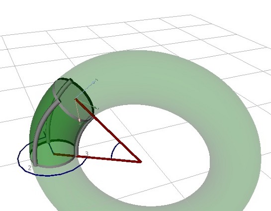
Since visualization requires to know the kinematics, we started working on that topic. Even if you can not compute the bending of infinitely many degrees of freedom, you can take the three length-sensors per segment and make some assumptions on how bending might occur. The most simple kind of bending is a circular shape. In three dimensions this corresponds to a torus:

The image shows how one segment with three actuator lengths (grey tubes) bends with a torus shape. Such a geometric transformation can be described by three parameters: two angles (shown in blue) and the radius of torus (shown in red). These three parameters can be reconstructed from the three actuator lengths. Once you have them, calculating the forward kinematics is simple. The only problem occurs when all lengths are equal, i.e. when the actuator is stretched. There is no torus to describe such behavior. This is a particular problem for the BHA since it allows ‘pure stretching’ movements without any bending. Yet, we found a nice, simple, and numerically safe way to deal with that ‘singularity’. Now, one can model the BHA by stacking multiple of such segments on top of each other.
Torus deformations are very, very simple compared to the real physics underlying continuum deformations. That is why they do typically not work as model for continuum robots, as found by several researchers (e.g. Trivedi 2008 [3] ).
Not so for the BHA! It works nicely.
Our evaluation shows that it reaches an average error of 1cm, opposed to a robot length on 1m. That is not perfect, but absolutely good enough for our purposes, and fully competitive with other continuum kinematics studies found in robotics literature.
This video shows how the model works, plus it gives some introduction about the actuation of the BHA:
The striking advantage of having a simple model is that it is really fast to execute. Our software library easily allows to compute the forward kinematics of the BHA with several 10kHz, even on a single CPU core. Although we didn’t plan to have such a model when we started working with the BHA, it has now become an essential tool for our work. Still, we do all important things on the real BHA, but can visualize and predict a lot of things in parallel now.
The kinematics simulation is written in C++ and available as open source. If you want to play around with it, do it. Just follow the instructions here to get library with the forward kinematics and the OpenGL-based 3D visualization shown above: http://www.cor-lab.de/software-continuum-kinematics-simulation
Just to give an impression … the following piece of code is all you need to compute the BHA’s kinematics:
// create robot morphology with segment radii 0.1, 0.09 and 0.08 metersContinuumRobotKinematics kinematics(RealVector(0.1, 0.09, 0.08));// specify an end effector offsetkinematics.setEndEffectorOffset(RealVector(0.0, 0.0, 0.14));// this is the forward kinematics function:Mapping<RealVector,RealVector> fwdKin = kinematics.getForwardPositionKinematics();// try out some posture (a combination of actuator lengths)RealVector posture = {0.2,0.24,0.24,0.2,0.24,0.24,0.2,0.24,0.24};// this is the resulting end-effector positionRealVector position = fwdKin(posture);// [-0.3808, 0, 0.686287]
And we got even more exciting stuff to show: To see our the real Bionic Handling Assistant and to see how we solved the above control problems with machine learning and managed to do cartesian control with the BHA, visit us at out booth on the Automatica fair in Munich: Booth 427 and 429 in exhibition hall B3, from May 22nd to 25th.
Contact:
- Dipl.-Inform. Matthias Rolf, CoR-Lab – Bielefeld University, mrolf@cor-lab.uni-bielefeld.de
- Prof. Jochen Steil, CoR-Lab – Bielefeld University, jsteil@cor-lab.uni-bielefeld.de
Matthias Rolf is researcher at the Research Institute for Cognition and Robotics at the Bielefeld University, Germany. His main research field is motor learning in developmental robotics.
1 thought on “Simulation of the Bionic Handling Assistant”